Port B of the MVME162P4 Z85230 serial communications controller is configurable via a serial interface module (SIM) that is installed at connector J15 on the board. Five serial interface modules are available:
EIA-232-D (DCE and DTE)
EIA-530 (DCE and DTE)
EIA-485/EIA-422 (DCE or DTE)
You can change Port B from an EIA-232-D to an EIA-530 interface or to an EIA-485/EIA-422 interface (or vice-versa) by mounting the appropriate serial interface module. Port B is routed (via the SIM at J15) to the 25-pin DB25 front panel connector marked SERIAL PORT 2.
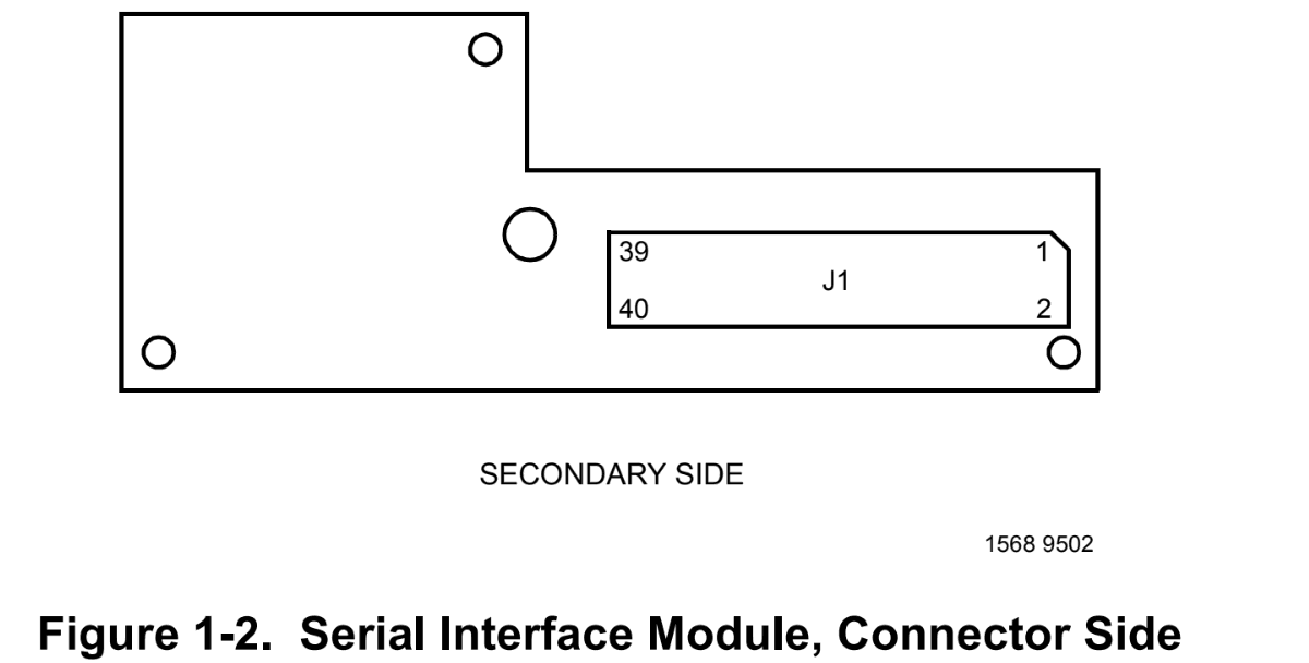
For the location of SIM connector J15 on the MVME162P4, refer to Figure 1-1. Figure 1-2 illustrates the secondary side (bottom) of a serial interface module, showing the J1 connector which plugs into SIM connector J15 on the MVME162P4. Figure 1-3 (sheets 3-6), Figure 1-4, and Figure 1-5 illustrate the seven configurations available for Port
For the part numbers of the serial interface modules, refer to Table 1-2. The part numbers are ordinarily printed on the primary side (top) of the SIMs, but may be found on the secondary side in some versions.
If you need to replace an existing serial interface module with a SIM of another type, go to Removal of Existing SIM below. If there is no SIM on the main board, skip to Installation of New SIM.
Removal of Existing SIM
1. Each serial interface module is retained by two 4-40 x 3 /16-in. Phillips-head screws in opposite corners. (Exception: SIMM09 is retained by one Phillips-head screw in the center of the module.) Remove the screw(s) and store them in a safe place for later use.
2. Grasp opposite sides of the SIM and gently lift straight up. Avoid lifting the SIM by one side only, as the connector can be damaged on the SIM or the main board.
3. Place the SIM in a static-safe container for possible reuse.
Installation of New SIM
1. Observe the orientation of the connector keys on SIM connector J1 and MVME162P4 connector J15. Turn the SIM so that the keys line up and place it gently on connector J15, aligning the mounting hole(s) at the SIM corners (or center) with the matching standoff(s) on the MVME162P4.
2. Gently press the top of the SIM to seat it on the connector. If the SIM does not seat with gentle pressure, recheck the orientation. If the SIM connector is oriented incorrectly, the mounting hole(s) will not line up with the standoff(s). Do not attempt to force the SIM into place if it is oriented incorrectly.
3. Place the one or two 4-40 x 3/16” Phillips-head screw(s) that you previously removed (or that were supplied with the new SIM) into the one center or two opposite-corner mounting hole(s). Turn the screw(s) into the standoff(s) but do not overtighten.
The signal relationships and signal connections in the various serial configurations available for ports A and B are illustrated in Figures 1-3 through 1-6.
Note: Model Number: MVME162P-344SE, Characteristics: 32MHz 68040, 16MB SDRAM, 2 SIO, 4 DMA IP, SCSI/Ethernet is used on Universal UIC HSP4797L Hitachi Sanyo TCM-X100 P.C.B. Mount 6300901030