Before beginning this procedure, ensure that the current Proper data has been received to the host computer.
1. Turn the power OFF to the machine.
2. Disconnect the electrical connector from the bottom of the camera.
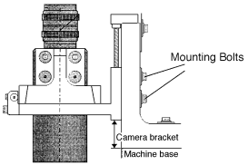
3. While holding the camera, remove the four mounting bolts located to the right of the camera as shown below and remove the camera from the machine.
Installation
1. Assemble the camera in the reverse order as previously stated.
2. Install the camera in the machine and attach the cable.
Mark Camera Focus Adjustment
1. Set the positions for the camera aperture and temporary focus according
to the camera type listed below.
Note: The collar thickness between the lens and the camera depends on the camera type.
Camera Type: 1 | Height: 35.0 mm | Aperture: 2 | Lens Type: 25 mm | Collar Type: 1:1.4 11.0 mm
Camera Type: 2 | Height: 24.0 mm | Aperture: 5 | Lens Type: 16 mm | Collar Type: 1:1.4 20.0 mm
Camera Type: 3 | Height: 20.0 mm | Aperture: 4 | Lens Type: 16 mm | Collar Type: 1:1.4 1.4 mm
Camera Type: 4 | Height: 17.5mm | Aperture: 2.8
Camera Type: 7 | Height: 17.5mm | Aperture: 2.8
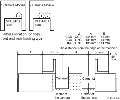
2. Set the clearance between the camera bracket and the edge of the base in the X-direction to 55 mm. (common for all camera types)
3. Loosen the parts camera fixing bolts and adjust the height from the machine base to the camera bracket using the height adjusting jackscrew, according to the following camera types.
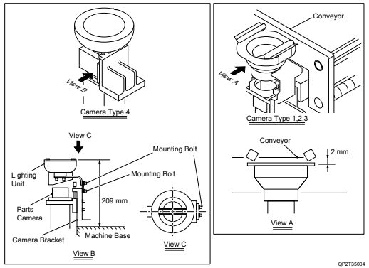
Lighting Position Adjustment for the Parts Camera
1. Camera type 1 to 3
X-direction: Not adjustable
Y-direction: Camera center
Z-direction: The top surface of the light bracket is 2 mm lower than the conveyor bracket.
2. Camera type 4 (Line Scan Camera)
X-direction: Not adjustable
Y-direction: Camera center
Z-direction: The height between the machine base and the glass surface of the lighting unit should be set at 209 mm.
The following is a list of Proper data measurements that must be performed after replacing the Parts Camera.
Camera Center XC/YC
Parts Camera X/Y Resolution
Placing Accuracy Measurement