Camera Center XC/YC (Temporary Measurement)
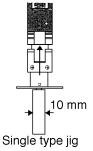
1. Mount a 10 mm nozzle in the holder.
CCD Camera: Back Light Nozzle
Line Scan: Front Light Nozzle
2. Execute the following command sequence to perform the automatic
measurement: [SET] – [PROPER] – [CAMERA] – [CAMERA POS] – [Partscam.#] – START and run the nozzle center check at least 3 times.
Note: Proceed to step 3 only if you receive vision processing errors.
3. After changing the camera it may be necessary to remeasure the camera / nozzle center position if the camera cannot detect the nozzle.
For line scan cameras align the nozzle center with the camera center by eye and execute the following sequence: [SET] – [PROPER] – [CAMERA] – [ACQUIRED POS] – [XC/YC] – [SET]. For CCD cameras execute: [SET] – [PROPER] – [CAMERA] – [ACQUIRED POS] – [XC/YC] and inch the nozzle to the center of the camera whilst verifying on the monitor and press [SET]. Proceed to run step 2 at least 3 times.
Parts Camera Focus (Camera Type 2 and 3)
1. Install a 10 mm back light nozzle.
2. [SET] – [MANUAL] – [VISION] – [ADJUST] and [GET ACQ] select the module number.
3. Select “parts camera” and “back light”.
4. Input 230 to “HEIGHT” and turn on the “Vacuum”.
5. Place a 108 pin (camera 2) or a 132 pin (camera 3) glass part on the nozzle.
6. Push START to move the head to the parts camera.
7. [DSP REAL-IMG] to display a real image.
8. If necessary repeat (6) – (8) to focus the camera.
9. If the camera is focused, push [ZOOM IN] several times until the pixel value numbers appear (Typically between 20 to 45).
10. Press: SCROLL <<<<< or >>>>> to view the leads.
11. Check the pixel values at the body and center of the lead.
12. Verify that the difference is less than 30.
Parts Camera Focus (Camera Type 4)
1. Install a 20 mm nozzle with 60 mm flourescent back plate attached.
2. [SET] – [MANUAL] – [VISION] – [ADJUST] – [GET ACQ] – [GET ACQ] and Press [CHANGE] to select module.
3. Select “parts camera” and “front light”.
4. Input 230 to “HEIGHT” and turn on the “Vacuum”.
5. Place a 248 pin glass part on the nozzle.
6. Push START to scan the image.
7. Press [ACQUIRED IMG] to display an image in memory and check focus.
8. Adjust the camera lens so that the glass part can be seen clearly.
9. If necessary repeat (6) – (8) to focus the camera.
10. If the camera is focused, push [ZOOM IN] several times until the pixel value numbers appear (Typically between 20 to 45).
11. Press SCROLL <<<<< or >>>>> to view the leads.
12. Check the pixel values at the body and center of the lead.
13. Verify that the difference is less than 30.
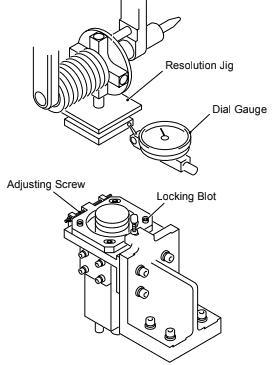
Parts Camera X/Y Resolution
1. Install the appropriate resolution jig (depending on camera type).
2. The resolution jigs and camera types are as follows:
Camera Type 1: 8.5 x 8.5 mm
Camera Type 2: 27.5 x 27.5 mm
Camera Type 3: 36.8 x 36.8 mm
Camera Type 4: 73.5 x 73.5 mm
Camera Type 7: 73.5 x 73.5 mm
3. Place a dial gauge on the X surface of the jig.
4. Move the X-axis and rotate the Q-axis to align the jig face parallel to the X-axis.
5. Tolerance needs to be less than 0.02/100 mm.
6. [SET] – [PROPER] – [ID CODE] – [Module No.] – [CAMERA] – [RESOLUTION] – [Parts Camera N] and push START to measure the resolution.
7. Verify that the Image Camera X/Y values are in range according to the chart below.
Camera Type 1 | Parts Camera X/Y: 1435238 ~ 1448346
Camera Type 2 | Parts Camera X/Y: 4633395 ~ 4672717
Camera Type 3 | Parts Camera X/Y: 6271795 ~ 6311117
Camera Type 4 | Parts Camera X/Y: 2942566 ~ 2955673
Camera Type 7 | Parts Camera X/Y: 2942566 ~ 2955673
Remarks: Parts Camera Q: 0 ± 655
8. If the Image Camera X/Y is not in range, adjust the height of the camera.
If Image Camera X/Y values are lower, the camera needs to be lowered.
If the Image Camera X/Y values are higher, the camera needs to be raised.
9. If the Image Camera X/Y values are in range, check the focus again.
10. If the focus is not good, adjust the focus and remeasure Image Camera X/Y resolution.
11. If the focus is good, verify that Image Camera Q is in range.
12. If Image Camera Q is not in range, adjust the camera angle.
13. Tighten the set bolts and verify that the Image Camera X/Y/Q values are within the ranges stated on the previous page.
Note: If vision errors occur during the Resolution calibration, repeat the focusing procedure.
Camera Center XC/YC (Final Measurement)
1. Mount a 10 mm nozzle in the holder.
CCD Camera: Back Light Nozzle
Line Scan: Front Light Nozzle
2. Because a real image cannot be displayed using a line-scan camera, align the monitor and nozzle center by eye using the inching function. For camera type 2 and 3 select [SET] – [PROPER] – [CAMERA] – [ACQUIRED POS] – [XC/YC] inch the nozzle to the center and [SET] the temporary camera center.
3. Execute the following command sequence to perform an automatic measurement: [CAMERA] – [CAMERA POS] – START.